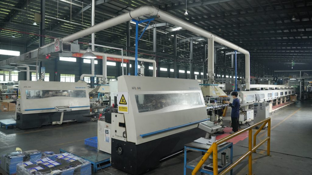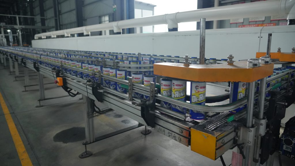
Aerosol can filling machines represent a specialized category of packaging equipment, typically divided into liquid filling systems and propellant filling (or aerosol charging) systems. Given the pressurized nature of aerosol products, the filling process is distinctly segmented into these two critical stages. The liquid filling unit is responsible for injecting a precise amount of product liquid into the can under standard atmospheric conditions. Subsequently, the aerosol charging unit introduces a metered volume of gas (or liquefied gas) under specific pressure into the same can. A key aspect of this process is that the can must be sealed before the propellant is added to ensure pressure integrity. Therefore, the charging apparatus injects the gas directly through the can’s valve located on the top.
Owing to the frequent handling of flammable and explosive substances in aerosol production—such as alcohols, solvents, and certain propellants—these machines are predominantly designed with fully pneumatic (air-powered) actuation systems. This deliberate design choice eliminates the risk of electrical sparks generated by motors or electrical components, thereby adhering to stringent fire and explosion safety standards.
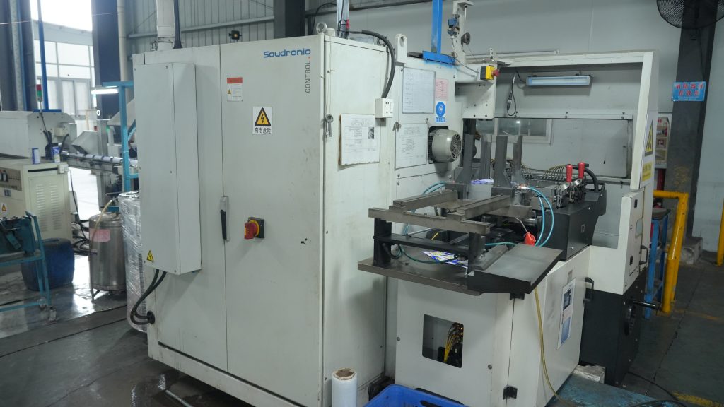
A basic or simplified aerosol filling line generally comprises several key components: a liquid filler, a seaming or crimping machine, a gas compressor or pump, a pressure booster pump, a worktable, a machine frame, and a suite of pneumatic control elements. The liquid filler itself consists of a liquid measuring cylinder and a filling nozzle. Similarly, the propellant filler includes a gas (or liquid propellant) measuring cylinder and a dedicated charging head. The measuring cylinders are usually mounted fixedly at the rear section of the worktable. In contrast, the liquid filling head, the crimper, and the propellant charging head are assembled on vertical columns, allowing for easy height adjustment to accommodate cans of various sizes. Modern systems often employ advanced dual-inlet/dual-outlet booster pumps, which feature larger diameter fluid lines for enhanced efficiency and flow capacity.

Liquid Filling Stage:
Upon activation of the liquid fill switch, a double air-controlled directional valve for the liquid metering cylinder shifts position. Compressed air then actuates a small cylinder, which mechanically opens the valve on the liquid filling head. Simultaneously, compressed air is directed into the upper chamber of the power cylinder (actuator for the metering piston), while the lower chamber vents. This action drives the piston downward, forcing the liquid from the measurement cylinder through the open filling head and into the awaiting aerosol can. As the piston reaches the bottom of its stroke, it triggers a pneumatic signal valve. The output pressure from this signal valve acts upon the double air-controlled valve, causing it to reverse. This reversal vents the upper chamber of the power cylinder and pressurizes the lower chamber, retracting the piston to refill the liquid chamber for the next cycle. The volume of liquid dispensed is precisely calibrated by adjusting the stroke length of the metering piston, typically via a threaded knob positioned atop the cylinder that sets the piston’s upper limit.
Crimping/Sealing Stage:
Activating the crimping switch shifts the crimper’s double air-controlled directional valve. This sends air into the upper chamber of the crimper’s lift cylinder, pushing its piston downward and forcing the crimping head onto the can’s valve cup to hold it firmly in place. As the cylinder descends fully, it contacts and triggers another pneumatic signal valve at the base of its travel. The output signal from this valve activates a single air-controlled directional valve. This valve then directs air into the upper chamber of the main crimping cylinder, causing its piston to extend downward. This piston is linked to crimping jaws that radially close around the can’s rim, sealing the valve cup onto the can body. Upon complete closure, a stopper or block on the crimping head assembly contacts a reset signal valve. This valve’s output pressure shifts the initial double air-controlled valve again. This change vents the lift cylinder’s upper chamber and pressurizes its lower chamber, retracting the entire crimping head upward. Concurrently, the single air-controlled valve resets, venting the upper chamber and pressurizing the lower chamber of the crimping cylinder, which retracts the piston and opens the crimping jaws, thus resetting the entire sealing unit.
Propellant Charging Stage:
The pressure booster pump, governed by compressed air and pneumatic logic controls, automatically draws liquid propellant (e.g., LPG, DME, or compressed gases) from a storage cylinder or tank. It pressurizes this propellant into a high-pressure liquid state and delivers it to the gas/propellant measuring cylinder. The output pressure of the liquid propellant is accurately regulated by adjusting the air supply pressure to the booster pump. When the gas charge switch is engaged, the double air-controlled valve on the gas metering cylinder shifts. This action first commands a small cylinder to lower the charging head onto the can’s valve, automatically opening a piercing nozzle. Simultaneously, air is fed into the upper chamber of the gas unit’s power cylinder (while the lower chamber vents), driving its piston downward. This piston pressurizes the propellant inside the measuring cylinder, forcing the precise dose of liquid propellant through the opened charging head and into the now-sealed aerosol can. The cycle completes when the piston triggers a signal valve, reversing the directional valve and retracting the piston to recharge the propellant chamber.
This detailed process ensures accurate, safe, and efficient production of aerosol products, leveraging robust pneumatic logic for precise control and operational safety in potentially hazardous environments.


